SteeringSystem
Steering System
Dear Reader: This article could be gingered up if you have knowledge in this area
Summary
AAmpere (amp), SI unit of electrical current steering systems consists of a steering control (tiller, wheel, joystick), linking mechanism (mechanical, electrical, digital, wireless) to the rudder control mechanism, stern post, rudder hinges and rudder blade. Mechanical linking can use cables, pushrods, or hydraulics. Steering systems must meet ABYCAmerican Boat and Yacht Council safety standards.
Sailboat
Smaller sailboats use a simple steering system with a tiller attached to the stern post. If you move the tiller to the left, the boat turns right; move the tiller right, and the boat goes left. A tiller is a horizontal arm that evolved from a steering oar.
Sailboats longer than 30 feet (9 meters) generally use a steering wheel. A mechanical linkage from the wheel controls the position of the rudder. Turn the wheel left and the boat goes to the left — turn right and the boat goes to the right.
Usually the linkage is a cable affair. On a larger sailboat the wheel also will be larger to provide greater mechanical advantage to the helmsman.
Possible failure points are:
- rudder blade from some mishap
- control cables
- quadrant arm on the stern post or rudder shaft
Powered Boat
In a powered boat, a steering system consists of a steering wheel or joystick on the bridge, a communications mechanism to the rudder control mechanism, and the rudder assembly itself.
Depending on their size, power boats use rack and pinion, rotary, or hydraulic steering. In larger boats (>greater than150 hphorsepower) electro-hydraulic steering rams are the standard control mechanism; although DCDirect current stepping motors are beginning to appear.
A wheel or joystick in the pilothouse has a sending unit to signal the rudder control. This can be an electrical signal relaying the position of the wheel or joystick, or a data network. Data networks are sexy, but they add complexity. They are used primarily to reduce build costs.
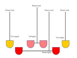
Consider a car which needs to control tail lights, brake lights and turn signals. In a classical system, i.e., older car, four separate power/control leads must be run from the front of the car, where the main electrical system is found, through the cabin of the car and into the trunk and rear fender areas.
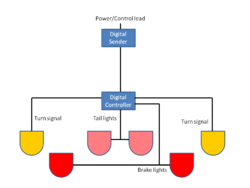
With a digital system, a controller is located in the rear area with power leads going to the lights. A single power/control lead is run from the front of the car to the rear. This is cheaper because digital components are cheap, copper wire is expensive, making wiring looms is expensive, and installing looms is expensive, relatively speaking.
The disadvantage is that when a digital unit fails, you can't repair it on the spot: you have to replace it. If it'sSecond advisable to keep a spare, then your inventory costs have increased.
Possible failure points are:
- sending unit at the helm
- electrical or digital network from sending to response units
- response unit on pump
- engine or electric motor to drive hydraulic pump
- hydraulic pump
- hydraulic ram
- rudder blade from some mishap
Emergency Steering
Steering is a vital single-point of failure, so a duplicate, backup or emergency steering system is advised.

